Projects
Marine HVAC and sewage solutions in action
AHU Reconstruction, Coil Renewal & Ductwork Restoration – Pax
A mid-size passenger ferry reported reduced cooling capacity, high humidity in guest areas, and visible corrosion inside several AHU sections. Our task was to carry out a complete engineering assessment and execute structural, mechanical, and insulation repairs to restore the Air Handling Unit to full operational performance.
Duct Construction, System Modification & Restoration – Pax Vessel
A RoPax vessel undergoing a hotel-area refit required new ducting to support updated ventilation layouts, along with repairs to several aging duct branches showing corrosion, leakage, and poor airflow distribution. The project involved fabrication of new duct sections, replacement of degraded fittings, restoration of airtightness, and on-site installation within restricted spaces.
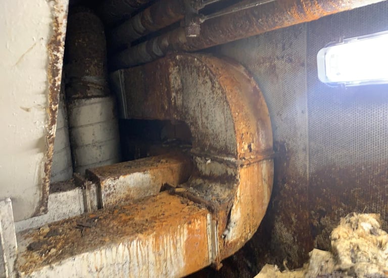
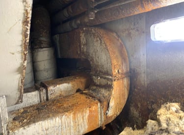
A technical inspection revealed several critical issues:
Severe corrosion in the bottom pans of the AHU, with multiple points of condensate leakage.
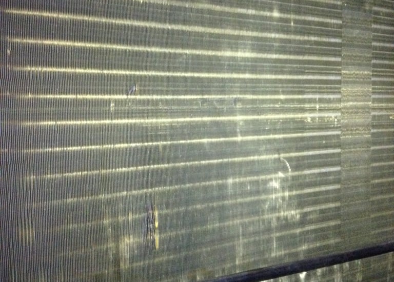
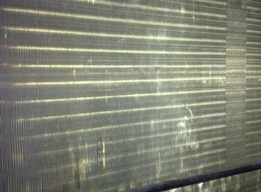
Cooling coil degradation, including reduced fin efficiency and partial blockage.
Air leakage at panel joints, access doors, and duct interfaces.
Damaged internal insulation with moisture absorption and mold growth.
Improper airflow due to misaligned baffles and deteriorated seals.
Airflow measurements showed a 22% reduction from design specification, and temperature drop across the coil was significantly below expected values.
1. Initial Assessment
2. Engineering Plan
A structured work plan was developed:
Disassembly of the AHU to access internal components.
Fabrication of new stainless-steel bottom pans, with redesigned drainage slopes.
Manufacture and installation of new cooling coils, engineered as direct-fit replacements.
Ductwork repair, including replacement of corroded sections and resealing of all joints.
Replacement of internal insulation with closed-cell Armaflex panels to prevent condensation.
Reconstruction of the casing, including panel reinforcement and realignment.
Functional testing, airflow balancing, and verification of condensate drainage.
All fabrication work followed marine HVAC construction standards and shipboard safety procedures.
3. Technical Execution
3.1 Bottom Pan Reconstruction
Old pans were removed and replaced with marine-grade stainless-steel pans custom-fabricated to match original dimensions.
Improvements included:
Increased slope angle for faster drainage
Enlarged drain outlets
Reinforced support structure
Full anti-corrosion treatment of surrounding frames
3.2 Coil Renewal
New coils were produced using copper tubes and high-efficiency aluminium fins.
The new coils were:
Pressure-tested at 25 bar
Installed with new brackets and gaskets
Commissioned and checked for thermal performance
Temperature drop improved to 94% of original design value.
3.3 Ductwork Repairs
Corroded duct segments were removed and replaced with galvanized sheet metal.
All joints were sealed using marine-grade adhesive and mechanical fasteners to achieve airtight Class B performance.
3.4 Insulation Replacement
All internal insulation was replaced with Armaflex closed-cell sheets, providing:
Improved condensation control
Mold resistance
Acoustic dampening
Longer service life in high-humidity environments
3.5 Final Assembly & Testing
After reassembly:
Airflow increased by 27%, restoring design performance.
Condensate drainage was stable with no leaks.
Temperature control in serviced areas improved significantly.
Visual inspection confirmed structural integrity and proper sealing.
4. Outcome
The refurbished AHU now operates at full efficiency with:
Eliminated corrosion points
Improved cooling capacity
Reduced energy consumption due to restored airflow
Extended service life (estimated +7–10 years)
Enhanced reliability in continuous marine operation
The customer reported immediate comfort improvements for passengers and reduced HVAC load on the chiller plant.
5. Key Technical Deliverables
New stainless-steel condensate pans (custom fabricated)
New cooling coils (OEM-equivalent performance)
Repaired and resealed duct sections
Closed-cell Armaflex insulation installation
Mechanical restoration of casing and sealing
Final performance verification report with measurements
During the technical inspection, the following issues were identified:
Corrosion and perforation in several supply and return duct sections, especially near the AHU discharge line.
Air leakage at flange joints, inspection hatches, and flexible connections.
Undersized branches causing airflow imbalance between cabins and public spaces.
Degraded internal insulation leading to condensation and localized dripping.
Deformed duct segments due to structural vibration and previous non-standard repairs.
The airflow survey documented an 18–32% loss in multiple branches compared to design flow rates.
1. Initial Assessment
2. Engineering Plan
A construction and repair plan was developed:
Fabrication of new galvanized and stainless-steel duct sections, sized according to system requirements.
Replacement of deteriorated branches and redirection of supply flows to match the updated layout.
Installation of new flanges, gaskets, access panels, and supports.
Sealing all joints using marine-grade sealant and mechanical fastening.
Installation of Armaflex insulation to prevent condensation and heat loss.
Airtightness testing and airflow balancing after commissioning.
The plan included coordination with the vessel’s refit contractor to ensure integration with ceiling, bulkhead, and cabin modifications.
3. Technical Execution
3.1 Duct Fabrication
All duct components were fabricated according to SMACNA / marine HVAC standards using:
Galvanized steel for general ventilation
Stainless steel in moisture-sensitive locations
Reinforced corners and stiffeners for long horizontal runs
Sections included rectangular ducts, transition pieces, elbows, branches, reducers, and splitter boxes.
3.2 Removal of Old Ducting
Degraded sections were removed without disturbing nearby cabling and piping.
Special care was required in:
Low-ceiling accommodation corridors
Areas with limited access behind paneling
Zones with pre-installed furniture and fire insulation
3.3 Installation & System Modification
New ducting was installed with:
High-strength hangers and vibration-isolated supports
New flanges with neoprene gaskets
Access doors for cleaning and inspection
Realigned airflow distribution boxes to match room layouts
All joints were sealed internally and externally for maximum airtightness.
3.4 Insulation & Condensation Control
Armaflex closed-cell insulation was applied to:
Cold supply ducts
Sections close to chilled-water coils
Ducts passing through unconditioned spaces
All seams were sealed to prevent condensation and microbial growth.
3.5 Final Testing & Balancing
After installation:
Airtightness test confirmed Class B+ performance
Airflow was balanced across all cabins and public areas
Noise levels were reduced due to improved insulation
Static pressure readings returned to within design range
4. Outcome
The ducting system now meets operational requirements with:
Restored structural integrity
Improved airflow distribution and cooling performance
Complete elimination of leakage points
Extended service life of ventilation circuits
Reduced load on AHUs due to improved efficiency
The vessel’s hotel areas reported a notable improvement in temperature stability and air quality.
5. Key Technical Deliverables
Newly fabricated duct sections (rectangular & round)
Transition pieces, elbows, reducers, and splitter boxes
Maritime-grade supports and vibration isolation
Armaflex insulation on all critical segments
Airtightness verification and airflow balancing report
As-built drawings for the modified duct paths
Contact
Reach out for expert marine HVAC help
technicalservice@shipairvac.com
+30 6944813721
ORESTIADA, Sterna Orestiadas SCHISTO INDUSTRIAL PARK Block 8, Street 6,
© 2025. All rights reserved.